A defence component can fail even when its measured dimensions appear acceptable: the datum scheme may be wrong, the gauge may be unsuitable, or a subcontracted heat-treatment record may not match the physical part. By the end, you will be able to examine a manufacturer’s workflow, measurement evidence, material traceability and process records to judge whether a tight-tolerance part is genuinely controlled.
Key takeaways
- Convert every critical drawing feature into a measurable inspection characteristic.
- Record heat numbers, material certificates, and condition before machining starts.
- Match tolerances to calibrated tools such as CMMs, gauges, and surface testers.
- Retain first-article, in-process, special-process, and shipment records together.
Start with the Drawing: Turn Design Intent into Inspection Requirements
A quality plan starts by translating the defence drawing into inspection characteristics, not by choosing a machine or measurement tool. Review the revision, notes, units, material condition, and every feature that affects fit, load, sealing, alignment, or interchangeability.
Build the datum structure exactly as the designer intended: use the ASME Y14.5 datum reference frame to establish how the part is oriented and constrained during inspection.
The drawing review should capture:
- Primary, secondary, and tertiary datums, including the surfaces, axes, or targets that establish the setup
- GD&T callouts for position, profile, perpendicularity, concentricity, runout, and flatness, with their tolerance zones and modifiers
- Critical-to-function dimensions, limit dimensions, unilateral tolerances, and basic dimensions controlled by geometric tolerances
- Surface-finish values and symbols, thread size, pitch, class, depth, form, and any required gauging method
- Requirements for hardness, coating thickness, non-destructive testing, marking, cleanliness, and special processes
Convert each callout into an operation in the inspection plan: identify the feature, datum setup, instrument or gauge, sampling frequency, acceptance limit, and record required. Re-zeroing on a convenient shop surface can conceal datum shift, fixture error, or runout that appears during assembly.
For results close to a limit, define a decision rule using measurement uncertainty; ISO 14253-1 provides the framework for avoiding automatic acceptance of a displayed value that measurement uncertainty could place outside tolerance. The completed plan then drives setup sheets, in-process checks, final inspection, and first-article evidence.
Build Material Traceability Before the First Cut
A correct mill test certificate proves only what was certified, not what is physically on the saw or machine table. Before release, match the incoming bar, plate, forging, or casting to its purchase order, drawing, material grade, temper or condition, dimensions, and certificate identity.
1. Record the heat number and lot number from the material itself, not from the delivery paperwork alone. Verify that the markings are legible and match the mill test certificate, packing list, and purchase order. Quarantine material with missing, altered, or conflicting identification.
2. Confirm the certificate contains the specified grade, chemical analysis, mechanical results, heat-treatment condition, and applicable standard or specification revision. If the contract calls for positive material identification (PMI), test the physical stock using a documented method and record the result against the heat number; PMI supplements the certificate rather than replacing it.
3. Transfer identity before cutting. Copy the heat number, lot number, and internal material-control number onto each cut blank, or maintain a controlled cut plan that links every blank to its parent piece. Mark remnants immediately, because an unmarked offcut can later be mistaken for an approved material.
4. Carry that identity through the router, traveller, inspection report, and final serial or batch record. Link each finished part to its blank, heat number, lot number, certificate, PMI result, and any approved material substitution.
Keep the chain intact when parts move to outside heat treatment or finishing; otherwise a valid certificate can be attached to the wrong component.
Match Each Feature to the Right Measurement Method
A defensible result matches the instrument to the feature, the datum scheme and the tolerance. Calibration alone is not enough: it links equipment to a national or international measurement standard, but does not prove suitable resolution, contact force, fixturing or operator method.
| Feature | Suitable method | Control that makes the result defensible |
|---|---|---|
| Linear dimensions and GD&T | Calibrated CMM | Verify machine length and probing performance to ISO 10360; control temperature, stylus, fixturing and probing strategy |
| Outside diameters | Micrometer | Verify range, resolution, contact force and zero; assess repeatability and reproducibility |
| Bores and internal diameters | Bore gauge | Set against a traceable master; control alignment and measure at specified depths and rotations |
| Threads, tapers and splines | Functional or attribute gauge | Use the drawing’s specified go/no-go or mating condition; record failures for investigation |
| Surface finish | Profilometer | Calibrate with a certified roughness specimen and use the drawing’s cutoff and evaluation length |
Recreate the drawing’s functional datum reference frame, not convenient shop surfaces. ASME Y14.5 defines the datum and geometric-tolerancing framework; re-zeroing incorrectly can conceal datum shift, runout or fixture error. A CMM report containing many decimal places proves nothing if the part has not reached inspection temperature.
For results near a limit, apply a documented decision rule under ISO 14253-1, using measurement uncertainty or a guard band rather than accepting every displayed value inside the tolerance.
- Record calibration status, certificate number, due date and traceability for every instrument.
- Use repeatability-and-reproducibility or uncertainty studies for critical measurements.
- Quarantine results made with overdue or failed equipment, then assess affected parts.
Prove the Process with First-Article and In-Process Controls
A conforming prototype does not prove repeatability. The manufacturer demonstrates production control by running the approved process, recording every critical characteristic, and showing that the same controls remain effective as tools, material, operators, and setups change.
1. Create a ballooned drawing that assigns a unique number to each dimension, GD&T callout, thread, surface finish, and critical-to-function feature. Link every balloon to an inspection result, work instruction, material record, and nonconformance decision.
2. Complete first-article inspection on parts made with production-intent material, tooling, fixtures, programmes, and inspection equipment. Under AS9102, the inspection report and supporting records show that the process—not a hand-finished sample—produced the conforming part.
Agree in the purchase and quality clauses when a full or partial re-accomplishment is required after a design, supplier, machine, tooling, or process change.
3. Inspect the first part after setup and compare it with the ballooned drawing before releasing the batch. Repeat checks at defined intervals and after tool changes, offsets, alarms, heat treatment, stress relief, or rework.
4. Control tool wear with tool-life limits, in-process probing, controlled workholding force, and first-off and last-off checks. Inspect after heat treatment when residual-stress release or distortion can move a feature outside tolerance.
5. Separate capability data by machine, tool, material lot, operator, and setup. Use control charts to establish statistical stability before calculating Cp or Cpk; a short, mixed dataset can disguise drift. For safety-critical features, specify 100% inspection or validated controls instead of relying on acceptance sampling.
Close the Chain with Special-Process Evidence and Shipment Records
Reject the packet if it proves only that the finished dimensions passed. A defensible release file links each part or lot to approved special-process records, final inspection results, nonconformance decisions and shipment identity.
1. Review the material and process chain. Confirm the part number, drawing revision, serial or lot number and material heat remain linked through heat treatment, plating, anodising and passivation. Match each certificate to the physical parts, not merely to a purchase order.
2. Check every special-process certificate against the purchase requirements. It should name the approved procedure and revision, processor, batch number, date, equipment or furnace identification, specified cycle or chemistry, actual results and qualified operator or inspector. For outsourced work, verify the processor’s approval status and scope.
3. Look for evidence that hidden damage was addressed. Depending on the drawing, review hardness and metallurgical results after heat treatment, coating thickness and adhesion records, corrosion or finish results, and non-destructive testing reports. Ask for records of shot peening, welding, brazing or EDM surface examination when those processes apply.
4. Reconcile the final inspection report with the drawing revision, datum scheme, critical dimensions, surface finish and agreed measurement decision rule. A value inside a limit is not enough if measurement uncertainty was ignored; ISO 14253-1 provides a recognised conformity approach.
5. Match the certificate of conformity, packing list, quantity, serial numbers, preservation method and shipping container labels. Resolve every open NCR, deviation or concession before acceptance.
Excellent Tools can use this same review discipline on precision parts and fixtures: the shipment packet must identify what was made, how it was processed and which evidence released it.
Related products
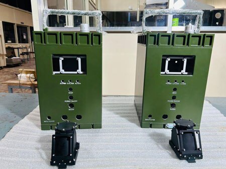 | Aerospace High Precesion Product 🔧 EXCELLENT TOOL TECH (Sheet Metal & Fixtures) • Located in Bhosari/Chakan, Pune — specializes in designing & manufacturing precision stamping... View product → |
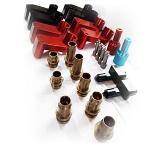 | Export Quality Industrial Precision Micron Components / Parts Jobwork Export Quality Industrial Precision Micron Components / Parts Jobwork We provide Export Quality Industrial Precision Micron Components / Parts Jobwork Services from of these products & our setup is situated in Pune,... View product → |
Frequently asked questions
How do you turn a defence drawing into inspection requirements?
Review the drawing revision, units, notes, material condition, and features affecting fit, load, sealing, alignment, or interchangeability. Convert each into an inspection characteristic with a defined method and acceptance limit.
What material records should you collect before machining?
Collect the material certificate, heat or batch number, supplier identity, specification, grade, condition, dimensions, and any required test results. Keep the records linked to the job and part serial numbers.
How do you choose the right measurement method for a tight-tolerance feature?
Use a calibrated method suited to the feature: a coordinate-measuring machine for complex geometry, micrometers or bore gauges for size, surface testers for roughness, and dedicated gauges for repeatable go/no-go checks.
Which records complete the quality chain before shipment?
Retain first-article and in-process inspection results, nonconformance dispositions, heat-treatment or coating certificates, final inspection records, packing details, and the shipment traceability record.
Related product
 | High precision parts Aerospace High precision parts View product → |