A press tool can meet its drawing dimensions and still produce parts with uneven burrs, distorted holes, springback, or assembly failures. By the end, you will know how to convert part tolerances into tool requirements, which inspection records to request, and how to separate genuine tool accuracy from a supplier’s machining claim.
Key takeaways
- Define tool tolerances from part function, material, and operation.
- Check punch-to-die alignment, clearance, and assembled-tool inspection records.
- Match accuracy requirements to blanking, piercing, bending, or forming operations.
- Track part quality from first setup through the tool’s service life.
What tool accuracy means beyond a dimension on a drawing
Tool accuracy is the ability of an assembled tool to produce acceptable parts repeatedly, not merely the dimensional accuracy of a punch or die measured on a bench. A die can pass its inspection while punch-to-die misalignment creates uneven clearance, burrs, hole distortion, side loading, and premature insert damage.
Compare manufacturers on these linked measures:
- Dimensional accuracy of working surfaces, datums, shut height, and clearance against the approved drawing.
- Concentricity of punches, bushings, and cutting features where a hole or profile depends on a common axis.
- Guide-post alignment under assembly, not just the measured size of separate guide components.
- Repeatability after removing and reinstalling the tool, including location in the press and feed system.
- Stability after sharpening, wear, and planned regrinding, with a stated regrind allowance and controlled datum.
Finished-part accuracy also depends on the process. A press-brake tool with correct dimensions can still produce the wrong angle when material springback, thickness variation, or machine deflection changes the bend. Acceptance testing must use the specified sheet and a representative cycle.
For progressive or compound dies, judge the relationships between the assembled components and the press feed; small errors can accumulate into hole-location drift or poor forming. Ask for evidence from a tryout, not only a component tolerance chart.
How to turn the sheet drawing into tool tolerances
Start with the part’s functional datums, not the die’s convenient machining references. Datum selection determines how every punch, die opening, guide, and forming surface relates to the features that control assembly.
1. Mark critical-to-function dimensions on the drawing: hole location, bend angle, flange height, wall thickness, shut height, and blank size. Convert each GD&T callout into a tooling requirement.
A hole’s true position controls punch and die location; flatness controls support and seating surfaces; profile tolerance controls the shape of a draw, bend, or contoured die face.
2. Set the punch and die relationship from the required clearance, material thickness, and cut-edge result. Specify punch-to-die concentricity, cutting-edge height, corner radii, and alignment at the working position. Do not copy the part tolerance blindly: include press deflection, material variation, springback, wear, and the process capability needed to hold the part.
3. Tie guide-post and guide-bushing locations to the same functional datum scheme. State allowable guide alignment, shut-height variation, and repeatability after tool removal and setup. A precise cavity with loose guidance still produces shifted holes, uneven burrs, or inconsistent bends.
4. Define forming-surface profile, radius, flatness, surface finish, and transitions as inspected characteristics. Finish critical dimensions after heat treatment, then record hardness and distortion; polishing cannot repair incorrect geometry.
5. Require a CMM report against the revision-controlled tool drawing, then demand a tryout using the intended press, sheet, lubrication, feed, and speed. Accept the tool against measured part results, not geometry alone. Include a controlled regrind allowance and the dimensions required after sharpening.
Why the operation changes the accuracy you need
The operation determines which error becomes a defect. In blanking and piercing, incorrect punch-to-die clearance or misalignment produces burrs, rollover, fractured edges, tapered holes and hole-location error. Check clearance against material thickness and grade, not against the toolmaker’s machining tolerance alone.
Bending and springback make finished-part accuracy depend on more than punch and die geometry. Material thickness, grain direction, die opening, punch-nose radius, machine deflection, crowning and angle compensation affect the final angle and inside radius. Drawing adds blank-holder force, lubrication and material flow: inaccurate radii or poor concentricity cause wrinkles, tearing, wall thinning and earing.
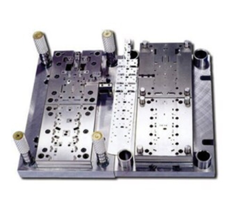
Progressive dies and compound dies create different alignment risks. A progressive die accumulates error through feed pitch, pilots, guide posts, stripper plates, inserts and press timing; the result can be station-to-station hole drift or uneven burrs even when each component passes inspection.
A compound die performs operations in one station, reducing transfer error but demanding accurate shut height, punch alignment and stripper movement. Transfer tools add gripper timing and datum-pickup errors as the part moves between stations.
Match your acceptance checks to the operation:
- Blanking and piercing: measure burr height, hole position, edge rollover and clearance marks.
- Bending: run the specified material through the intended press and record angle, radius and springback.
- Drawing: inspect wall thickness, wrinkles, splits, flange height and concentricity.
- Progressive, compound and transfer: verify feed pitch, pilot engagement, station datums and part-to-part repeatability.
Which records prove that a completed tool is accurate
A stated machining tolerance proves only what the supplier intended to cut, not what the completed tool measures or how it performs in production. Request records with actual values, drawing revision, datum references, equipment identification, calibration status, measurement uncertainty where relevant, and inspection conditions.
| Record | Request | What it proves |
|---|---|---|
| CMM inspection report | Measured punch, die, guide alignment, profiles, positions, and clearances against datums | Finished geometry under inspection conditions; not production part capability |
| First-off inspection | Initial stamped-part dimensions, hole locations, burr height, bend angle, and surface defects | Whether the first approved part meets the drawing |
| Tryout report | Intended press, material grade and thickness, lubrication, feed, speed, setup, samples, and corrective actions | Tool performance under defined manufacturing conditions |
| Capability data Cp and Cpk | Characteristic, specification limits, sample size, sampling method, and process conditions | Short-run variation and centring; not proof against wear or setup changes |
Reject a report that says only “within tolerance.” Ask whether critical dimensions were finished after heat treatment, and request hardness, distortion, and stress-relief records for punches, dies, and inserts.
Match the first-off inspection to the CMM report through the same revision-controlled drawing and datum scheme. A CMM pass can still produce bad parts if press alignment, shut height, guides, material variation, or lubrication introduces error; the tryout report exposes that gap.
For aerospace or defence work, AS9100 certification does not replace defined critical characteristics and functional acceptance criteria.
How to judge accuracy over setup, production, and tool life
A tool earns trust only if it produces conforming parts after a controlled setup change, across the intended press range, and near the end of its service interval. Judge the manufacturer by evidence from those conditions, not by one dimensional inspection.
1. Request a repeatability trial using the production press, material grade, thickness, lubrication, feed settings, and speed. Record part dimensions, burr height, hole position, bend angle, and springback before and after dismantling and reinstalling the tool.
2. Ask how press-to-tool alignment is checked after assembly. Look for datum-based alignment records, shut-height verification, punch-to-die concentricity checks, and gauge repeatability data. Calibration certificates must identify each measuring device, its serial number, and expiry date.
3. Require process capability results tied to named characteristics and specification limits. Ask for the sample size, sampling interval, press settings, material lot, and Cp or Cpk calculation; a short stable trial proves little if wear or setup variation is excluded.
4. Examine the maintenance plan for insert replacement, guide wear, clearance checks, and regrinding. The supplier must state the regrind allowance, the datum restored after each grind, the inspection steps, and the expected tool life before replacement.
5. Ask for failure records showing the response to burr growth or dimensional drift. Excellent Tools, for example, can be assessed by whether its qualification package links tryout results to controlled maintenance and regrind decisions rather than promising accuracy alone.
Related product
 | Sheet Metal Press Tools Manufacturer Sheet Metal Press Tools Manufacturer Press tools are commonly used in hydraulic, pneumatic, and mechanical presses to produce the sheet metal components in large volumes. View product → |
Frequently asked questions
What does tool accuracy mean in sheet metal pressing?
Tool accuracy means the assembled punch, die, guides, and inserts produce acceptable parts repeatedly, not simply that individual components match a drawing.
How do you convert a sheet metal drawing into tool tolerances?
Start with critical part dimensions, geometric tolerances, material thickness, and functional requirements, then allocate tolerances across the tool, setup, and process.
Why does the pressing operation affect the accuracy required?
Blanking, piercing, bending, and forming create different risks, including burrs, hole distortion, springback, uneven angles, and surface damage.
Which records demonstrate that a completed press tool is accurate?
Request dimensional inspection reports, coordinate-measuring-machine results, alignment checks, first-off part measurements, and records showing the tool was tested in its assembled condition.
How can you judge tool accuracy throughout tool life?
Compare first-setup results with production measurements, monitor burr height and critical dimensions, inspect wear, and record adjustments, sharpening, and insert replacement.